

Saturn Car Stereo Receiver Installation wiring connection procedure
Before installation of this car stereo receiver, please note the following precautions. In most cases car stereo installation will be as simple as connecting your new car stereo receiver to your vehicle connections, however it is not always that straight forward and there are also some ancillary wiring connections to be taken into consideration.


Wiring color for car stereo connection
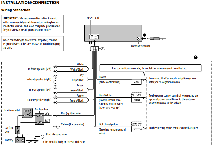
B+ Battery Wire (Yellow)
Connect this wire to the positive (+) post of the vehicle’s battery. Memory Power (12V direct from Battery). Connects the radio directly to the battery. Requiring an uninterrupted feed to retain the memory such as EQ and Preset Radio stations whilst the ignition is off.
ACC Switched Power Wire (Ignition) (Red)
Connect this wire to an open terminal on the vehicle’s fuse box or another unused power source which provides (+) 12V only when the ignition is turned on or in the accessory position. +12V Main Power (Switched via Ignition key). +12 V with the ignition key is in the ACC or ON position. Switched referred to as ACC, in most cases this can be easily found next to the Ground in a standard ISO, however some vehicles wok on a reversed wire set up requiring the Red and Yellow to exchange places, In more modern vehicles with CAN controlled ACC switch there is no ignition wire. To locate the correct connections use a multimeter to ascertain which wire from your vehicle provides a permanent 12v feed this should be connected to the Yellow Wire. From here you will need to source an ACC feed for the Red Wire. In general this can be found in the vehicle connection, with the exception of CANbus in these cases if your cigarette socket is only live when the ignition is on you can take the feed from here alternatively a little time and investigation is needed to source a feed directly from the fuse box.
GND Ground Wire (Black)
Connect this wire to a good chassis ground on the vehicle. Make sure the connection is made to bare metal and is securely fastened using the sheet metal screw provided. The most important connection of all, without a solid Ground the unit will not function correctly, generally this is a standard position on an ISO connection.
ANT Power Antenna Wire (Blue)
Connect this wire to the +B terminal of your power antenna, if applicable. Power for Electric Antenna. Output from the stereo +12 V (maximum 150 – 300mA) power supply for automatic or electronic antennas.
REM Remote Turn-On Wire (Blue/White)
Connect this wire to the remote turn-on wire of your amplifier or signal processor.
ILLUMINATION DIMMER Illumination Wire (Orange)
This wire may be connected to the vehicle’s instrument cluster illumination wire. This will allow the backlighting of this unit to dim whenever the vehicle’s lights are turned on. Dial-light illumination (car side light circuit). +12 V input on the car when the lights are on. For some it actually illuminates the radio display – the others can dim the lights. If the dashboard of your car has a light control function, this pin should be connected in order to regulate the brightness. The wire from lighting a cigarette lighter can be used for the same purposes.
SCV Speed-dependent volume control, speed signal
This pin is used in some radio equipment to automatically boost up the volume. It needs the output from the speed sensor. Note: If the speedometer stops working when the radio is connected, then the pin is probably grounded because radio probably uses this pin for another function, except for GALA.
MUTE Mute from Cell-Phone
This pin is used to silence the audio cd, earthed by some other external components such as a mobile phone that is connected to the radio.
REV the reversing light switch
+12 V input on the radio with the ignition switched on the ignition and the car is in gear to move backwards. Used for reversing lamp signal on Becker radios with navigation.
WARNINGS
• If you connect the ignition wire (red) and the battery wire (yellow) to the car chassis (ground), you may cause a short circuit, that in turn may start a fire. Always connect those wires to the power source running through the fuse box.
• Do not cut out the fuse from the ignition wire (red) and the battery wire (yellow). The power supply must be connected to the wires via the fuse.
CAUTION
• Install this unit in the console of your vehicle. Do not touch the metal part of this unit during and shortly after the use of the unit. Metal part such as the heat sink and enclosure become hot.
NOTE
• Mounting and wiring this product requires skills and experience. For best safety, leave the mounting and wiring work to professionals.
• Make sure to ground the unit to a negative 12V DC power supply.
• Do not install the unit in a spot exposed to direct sunlight or excessive heat or humidity. Also avoid places with too much dust or the possibility of water splashing.
• Do not use your own screws. Use only the screws provided. If you use the wrong screws, you could damage the unit.
• If your car’s ignition does not have an ACC position, connect the ignition wires to a power source that can be turned on and off with the ignition key. If you connect the ignition wire to a power source with a constant voltage supply, such as with battery wires, the battery may be drained.
• If the console has a lid, make sure to install the unit so that the front panel will not hit the lid when closing and opening.
• If the fuse blows, first make sure the wires aren’t touching to cause a short circuit, then replace the old fuse with one with the same rating.
• Insulate unconnected wires with vinyl tape or other similar material.
To prevent a short circuit, do not remove the caps on the ends of the unconnected wires or the terminals.
• Secure the wires with cable clamps and wrap vinyl tape around the wires that comes into contact with metal parts to protect the wires and to prevent short circuit.
• Connect the speaker wires correctly to the terminals to which they correspond. The unit may be damaged or fail to work if you share the wires or ground Installation them to any metal part in the car
When only two speakers are being connected to the system, connect the connectors either to both the front output terminals or to both the rear output terminals (do not mix front and rear). For example, if you connect the connector of the left speaker to a front output terminal, do not connect the connector to a rear output terminal.
• After the unit is installed, check whether the brake lamps, blinkers, wipers, etc. on the car are working properly.
• Do not press hard on the panel surface when installing the unit to the vehicle. Otherwise scars, damage, or failure may result.
• Reception may drop if there are metal objects near the Bluetooth antenna. Bluetooth antenna unit Supplied accessories for installation
Installation procedure
1) To prevent a short circuit, remove the key from the ignition and disconnect the terminal of the battery.
2) Make the proper input and output wire connections for each unit.
3) Connect the wire on the wiring harness.
4) Take Connector B on the wiring harness and connect it to the speaker connector in your vehicle.
5) Take Connector A on the wiring harness and connect it to the external power connector on your vehicle.
6) Connect the wiring harness connector to the unit.
7) Install the unit in your car.
8) Reconnect the terminal of the battery.
ISO connector for car stereo receiver installation

‘KL’ is the abbreviation for ‘klemme’ which is the German term for connector/connection, or ‘Klemmenbezeichnungen’. Klemmenbezeichnungen means Terminal designations.
This is mostly encoded in the German standard DIN 72552 – “Standard for labelling the electric terminals in automotive wiring.”.
However, in short, the KL codes you are most likely to want to know about are:
KL15 is ignition switch position #2 (on)
KL30 is battery positive, there will be ’12 VDC’ on this at all times
KL31 is battery negative, (unswitched)
KL50 is ignition position #3 (start)
KLR means ignition switch position #1 (Accessory) In this mode the radio/IVI, windows, etc will be powered on, but the traction motor will not be enabled (ICE or EV), there may be limited HVAC (Heating Ventilation and Air Conditioning) due to the HVAC compressor, and the heater not being powered.
Normally when talking about KL30 and KL31, it is the positive and negative poles of the 12V (or 24V) vehicle battery.
ISO A connector power supply wiring
ISO B connector speaker output wire
RF+ Right Front (+) Speaker Output Wire (Gray)
RF- Right Front (−) Speaker Output Wire (Gray/Black)
RR- Right Rear (−) Speaker Output Wire (Violet/Black)
RR+ Right Rear (+) Speaker Output Wire (Violet)
LR+ Left Rear (+) Speaker Output Wire (Green)
LR- Left Rear (−) Speaker Output Wire (Green/Black)
LF- Left Front (−) Speaker Output Wire (White/Black)
LF+ Left Front (+) Speaker Output Wire (White)
ISO connector wiring diagram for auto radio car stereo pinout

ISO 10487 connector
ISO-A connector (Power)
| Pin | Signal |
| 1 | Speed signal (speed-dependent volume control) |
| 2 | Phone Mute |
| 3 | Reversing light switch (used for satellite navigation) |
| 4 | +12V from Battery |
| 5 | Power for electronic Antenna (+12V output 150-300mA) |
| 6 | Illumination (+12 V input when the lights are on) |
| 7 | +12V Power (Switched via Ignition key) |
| 8 | Ground |
On some cars the +12V Ignition and Battery positions are reversed
ISO-B connector (Loudspeaker)
| Pin | Signal |
| 1 | Right Rear + |
| 2 | Right Rear – |
| 3 | Right Front + |
| 4 | Right Front – |
| 5 | Left Front + |
| 6 | Left Front – |
| 7 | Left Rear + |
| 8 | Left Rear – |

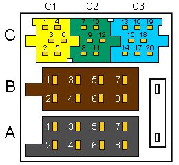
ISO-C connector [mini-ISO]
C1 (external amplifier)
C2 (remote control)
C3 (CD changer)
| Pin | Signal |
| 1 | Line out Rear Left |
| 2 | Line out Rear Right |
| 3 | Line out common Ground |
| 4 | Line out Front Left |
| 5 | Line out Front Right |
| 6 | +12V switched (max 150mA) |
| 7 | Receive Data |
| 8 | Transmit Data |
| 9 | Chassis Ground |
| 10 | +12V switched (max 150mA) |
| 11 | Remote control In |
| 12 | Remote control Ground |
| 13 | CDC Data In |
| 14 | CDC Data Out |
| 15 | CDC +12V permanent |
| 16 | CDC +12V switched (max 300mA) |
| 17 | CDC Data Ground) |
| 18 | CDC Audio Ground |
| 19 | CDC Audio Left |
| 20 | CDC Audio Right |
ISO 10487 only defines the physical attributes
of the connectors, not the pin/signal designations.
The connector wiring depends on the manufacturer.
Warning
Citroen cars can use ISO connectors on their audio systems, however
extreme care should be taken as these connectors DO NOT follow the
standard UK connection used in many ISO harnesses. If the supplied lead
is plugged directly into the vehicle dashboard various faults may occur.
Faults may range from inaccurate dashboard readings to complete failure
of the BSI unit – resulting in a costly repair. When sourcing an ignition supply
the first option should be the cigarette lighter socket. If this is unavailable or
inconvenient then seek a suitable supply at the fuse box. DO NOT expect
an ignition source at the ISO connector. The multiplexed wiring found on
these vehicles do show a 12v feed at ignition on the ISO connector but
this is normally a CAN wire and not ignition. Connection to this wire is not
advised as it may cause damage to the vehicles BSI unit. Please refer to the
owners manual for wiring detail.
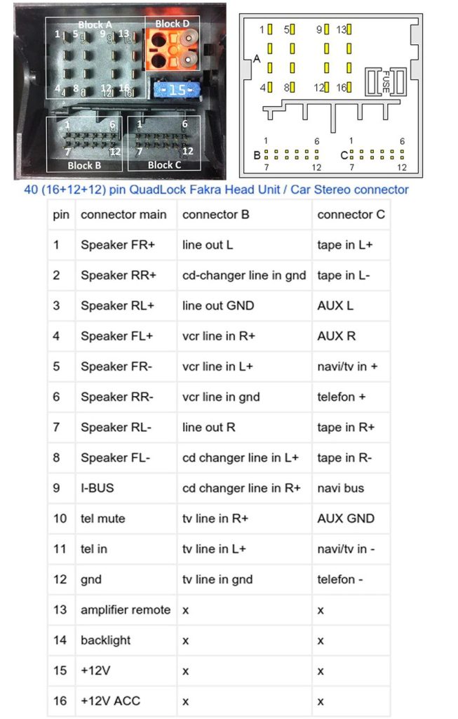
Quadlock connector for car stereo installation and connection

From 2000 and onwards, manufacturers, such as BMW, Citroën, Ford, Mercedes Benz, Peugeot, Volkswagen, Rover, Audi, SEAT, Opel or Škoda have sometimes started using a 40-pin connector instead, called the Quadlock.
The Quadlock connector is a standard automotive connector used in car audio systems. The pins in the connector are labeled with numbers or letters, which correspond to the specific function of the wire.
It’s important to keep in mind that these functions may vary depending on the specific make and model of the vehicle, as well as the type of stereo being installed. Therefore, it’s always a good idea to consult the wiring diagram for your specific car and stereo to ensure that you are connecting the wires correctly. Some quadlock connectors also have different pin arrangements, some may have the pins in a different order, some may have missing pins or extra pins, so always check the wiring diagram for your specific car and stereo.
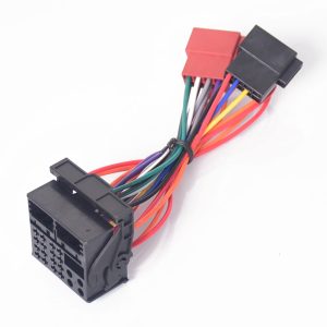
Using a wiring harness adapter can make the process of connecting the wires much easier, as it eliminates the need to match each wire individually and allows for a plug-and-play installation.


Car stereo Speaker Adapter As the interior aesthetics of today’s cars change, many vehicle manufacturers are using irregular shaped/sized speakers in doors and interior panels. Speaker Adapter allows the fitment…
Car camera rear view backup Car cameras, also known as dash cameras or dashcams, are becoming increasingly popular among drivers. These cameras are mounted on the dashboard or windshield of…
Antenna Adaptors When replacing an original equipment stereo, it may be necessary to adapt the antenna connection to enable aftermarket head unit fitting. A range of antenna adaptors is available…
Stalk control adaptors allow aftermarket car stereos to be fitted in a vehicle where the original car stereo was installed using a stalk control. These adaptors provide a connection between…
Connecting steering wheel audio controls to a new car stereo can be a bit more complex than just installing the stereo itself. Here are the general steps for connecting steering…
A Bluetooth adapter for a car stereo is a device that allows you to wirelessly stream music from your smartphone or other Bluetooth-enabled device to your car’s stereo system. Here…
CANbus Interfacing The evolution of CANbus systems on vehicles has given rise to the need for a range of Interfaces so as to obtain key functionality from the systems. Data…


